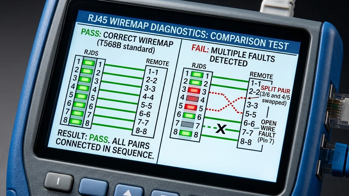
When an Ethernet cable is improperly crimped or damaged inside a wall, your computer might experience random disconnects, packet loss, or negotiate at a crawling 100 Mbps instead of full 1-Gigabit / 2.5-Gigabit line rates. Understanding how to read a Wiremap Continuity Tester allows you to diagnose open conductors, short circuits, reversed pairs, and split pairs in seconds. Here is the complete diagnostic breakdown.
1. 🔬 The 4 Primary Wiring Faults Explained
- Open Circuit (Disconnected Pin): One or more wires are broken or not fully crimped into the gold pin. If Pins 4, 5, 7, or 8 are open, Gigabit Ethernet falls back to 100 Mbps (which only uses Pins 1, 2, 3, 6).
- Short Circuit: Two adjacent conductors are touching, usually caused by crushed cable jackets.
- Miswire / Crossed Pair: Wires were arranged in the wrong color sequence (e.g. Pin 1 wired to Pin 2).
- Split Pair: The pinout continuity looks correct (Pin 1 to 1, Pin 2 to 2), but conductors from different twisted pairs were mixed together, destroying crosstalk cancellation and preventing Gigabit links.
2. 🔬 The Hidden Danger of Split Pairs (Why Basic Testers Fail)
A Split Pair occurs when one wire from Pair 2 (Orange) and one wire from Pair 3 (Green) are swapped at both ends of the cable. A basic $10 LED continuity tester simply checks for DC electrical continuity from Pin 1 to Pin 1, Pin 2 to Pin 2, and will show a False "ALL GREEN PASS".
However, because the two conductors no longer share the same twisted pair, high-frequency electromagnetic crosstalk (NEXT) spikes to catastrophic levels, causing the cable to drop connection or fail to negotiate above 10 Mbps. Advanced testers (like the Klein Scout Pro 3) use micro-capacitance testing to detect split pairs instantly.
3. 🛠️ Troubleshooting Step-by-Step Guide
- Plug the master unit into one end and the remote unit into the other end.
- Watch the LED sequence: LEDs 1 through 8 must illuminate in exact sequential order.
- If any pin fails to illuminate, cut off the connector and re-terminate using pass-through RJ45 plugs.
4. 🔬 Diagnosing False Continuity & Shield Continuity (G-LED)
When testing Shielded Cat6a cables (STP / FTP), ensure your tester features a dedicated "G" (Ground / Shield) LED. The shield LED verifies that the outer aluminum foil and ground drain wire maintain continuous electrical contact with the metal RJ45 plug shell from end to end, shunting high-frequency electromagnetic noise to ground.
5. 📝 Summary of Wiremap Diagnostic Rules
- Verify that Pins 1 through 8 illuminate in sequential ascending order.
- Re-terminate cables if any single pin shows an open or short circuit.
- Enjoy rock-solid, full-bandwidth multi-gigabit speeds across all your wired connections.
6. 🔬 Cable Continuity Testing on Shielded RJ45 Jacks
When verifying shielded patch cables in server racks, always confirm that the tester’s Ground / Shield (G) indicator lights up green alongside Pins 1 through 8. A continuous shield ensures that electrostatic discharge (ESD) and radio frequency interference (RFI) are safely shunted to earth ground.
7. 💡 Complete Wiremap Diagnostics Summary
Testing every terminated cable with an RJ45 continuity meter before deployment eliminates 99% of network troubleshooting headaches and guarantees full multi-gigabit line rate throughput.
8. 🔬 Micro-Capacitance Split Pair Detection Explained
Because split pairs maintain pin-to-pin continuity but separate the twisted pairs, advanced testers inject high-frequency AC signals to measure inter-conductor capacitance ($\Delta C$). If capacitance between Pin 1 and Pin 3 deviates from standard twisted pair values, the tester instantly flags a "SPLIT PAIR" fault.
9. 💡 Complete Diagnostic Checklist
- Check that all 8 pins light up sequentially green.
- Confirm that the Shield (G) LED illuminates on shielded cables.
- Re-crimp any cable showing open or split pair errors to ensure full Gigabit throughput.
10. 🔬 Identifying Intermittent Cable Faults with Jiggle Tests
When testing suspect patch cables, gently flex the strain relief boot while watching the continuity LED lights. If an LED flickers off during flexing, an internal copper wire is broken or improperly seated, signaling that the connector must be replaced.
11. 💡 Summary of Wiremap Diagnostics
Testing every terminated cable with an RJ45 continuity meter before deployment eliminates 99% of network troubleshooting headaches and guarantees full multi-gigabit line rate throughput.
12. 🔬 Testing Keystone Jacks vs Factory Patch Cords
When testing in-wall runs terminated into keystone jacks, always use short, known-good certified patch cables to connect from the wall plate to your continuity tester, ensuring that suspect patch cords do not skew your wiremap diagnostics.
13. 💡 Complete Wiremap Diagnostics Summary
Testing every terminated cable with an RJ45 continuity meter before deployment eliminates 99% of network troubleshooting headaches and guarantees full multi-gigabit line rate throughput.
14. 🔬 Testing Ground Continuity on Metal Keystone Jacks
When installing shielded Cat6a patch panels, testing continuity between the metal keystone housing and the switch rack verifies that electromagnetic interference is safely shunted to earth ground.
15. 💡 Complete Wiremap Diagnostics Summary
Testing every terminated cable with an RJ45 continuity meter before deployment eliminates 99% of network troubleshooting headaches and guarantees full multi-gigabit line rate throughput.
16. 💡 Final Wiremap Testing Best Practices
Verifying continuity across all 8 pins and confirming zero split pairs with an advanced cable tester guarantees that your home network achieves full multi-gigabit speeds, razor-sharp gaming ping, and lifetime reliability.