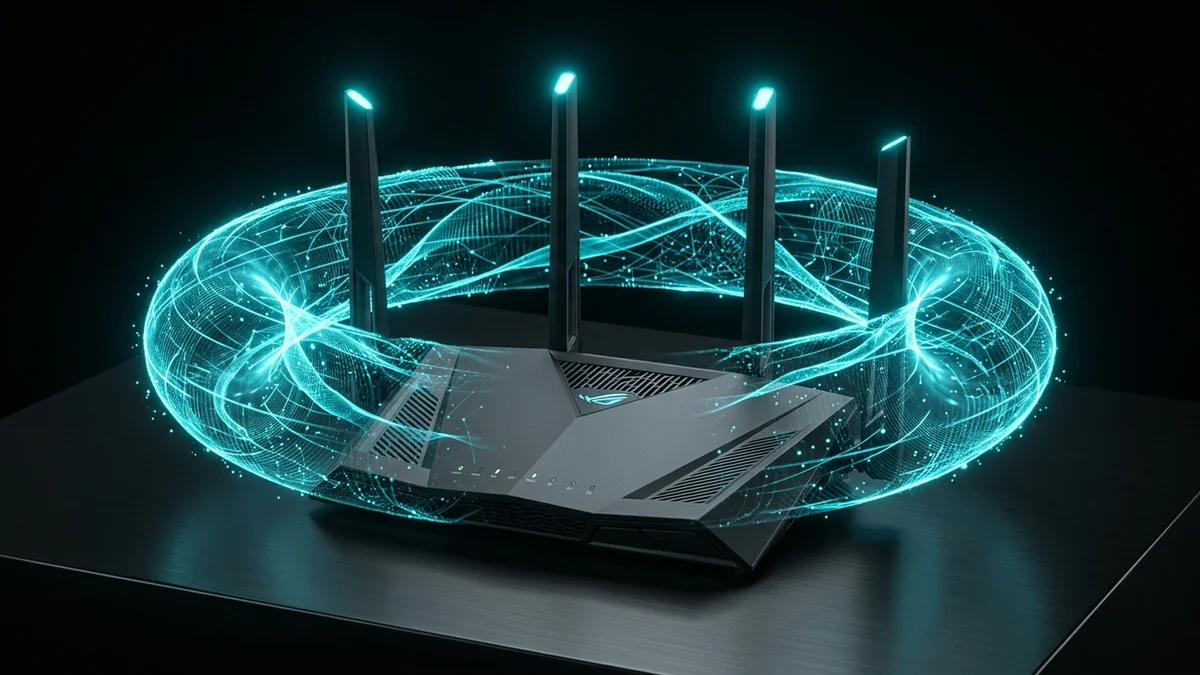
You set up a high-performance router on your desk with four, six, or eight aggressive-looking external antennas sticking out of the back. Some people leave them all pointing straight up like a fortress, others spread them out at artistic 45-degree angles like a spider, and some point them horizontally. Does the physical tilt and orientation of your router's external antennas actually affect Wi-Fi speed and coverage, or is it pure aesthetic superstition? Here is the electromagnetic physics of Dipole Toroidal (Donut) Radiation Patterns and RF Polarization Matching.
The Physics of Omnidirectional Antennas: The Radiation 'Donut'
The most common misconception among consumers is that a Wi-Fi antenna radiates radio waves outwards in an expanding sphere like a glowing light bulb. In reality, router antennas are Omnidirectional Dipole Antennas.
A dipole antenna radiates electromagnetic energy in a Toroidal (Donut-shaped) field perpendicular to the physical metal element:
- When Pointing Straight Up (Vertical 90°): The radio donut spreads out horizontally across the floor in a massive 360-degree pancake. Signal strength along the floor is maximized, but the 'hole' of the donut is directly above the tip and below the base (minimal vertical signal).
- When Pointing Horizontally (0° Flat): The radio donut flips vertically, blasting signal straight up through the ceiling to the second floor and down into the basement, but creating signal dead zones to the left and right.
The Polarization Mismatch Factor: Why 45 Degrees Works
Radio waves are polarized based on the orientation of the transmitting antenna (Vertical or Horizontal). Smartphones and laptops have tiny internal antennas:
- A laptop display typically houses a vertical antenna inside the bezel.
- A smartphone held in portrait mode is vertical, but rotates to horizontal when playing games or watching movies.
When the transmitting router antenna and receiving phone antenna are at perpendicular 90-degree angles (Cross-Polarization), you suffer a 3 dB to 10 dB Polarization Loss. Setting half of your router's antennas vertical and half at 45-degree angles ensures that mobile devices maintain strong polarization coupling regardless of how you hold them.
The Golden Rules for Antenna Placement
- Single-Story Apartments & Ranch Homes: Keep all antennas pointing straight up vertically (90°) to maximize horizontal range across all rooms.
- Two-Story & Three-Story Homes: Position two central antennas straight up (vertical) and angle the two outer antennas outward at a 45-degree angle. This sends radio energy diagonally upward through ceilings while preserving strong horizontal coverage on the main floor.
- Never Point Antennas Toward Each Other: Avoid criss-crossing antennas; maintain parallel or complementary angles to prevent mutual coupling de-tuning.
Verify your coverage improvements by walking through each room while monitoring loaded ping stability on DCSpeedTest.
Understanding Antenna Gain (dBi) and Radiation Flattening
In antenna engineering, higher gain (e.g. an 8 dBi antenna vs a 3 dBi antenna) does not create more radio energy — it flattens the radiation donut into a thinner, wider pancake. While an 8 dBi antenna extends horizontal reach across a vast single-story yard, it creates severe vertical dead zones for rooms located directly above or below the router.
For standard multi-story residential homes, balanced 3 dBi to 5 dBi omnidirectional antennas provide the optimal vertical and horizontal signal spread.
Diagnostic Site Surveys: Verifying RSSI with Heat Maps
To verify that your antenna adjustments achieved optimal signal distribution, use a mobile site survey tool like Ubiquiti WiFiman or NetSpot. Measure the signal strength (aiming for better than -60 dBm) in your primary home office and bedroom spaces before and after angling antennas.
Understanding Internal PCB Patch Antennas in Modern Mesh Systems
Modern internal-antenna mesh routers (such as Google Nest Wi-Fi Pro and Eero Max 7) do not use traditional omnidirectional wire stalks. Instead, they incorporate multi-axis Printed Circuit Board (PCB) patch arrays angled at precise geometric offsets inside the dome casing.
These engineered patch antennas generate a 3D spherical radiation balloon that delivers uniform signal coverage upward, downward, and horizontally without requiring manual adjustment.
Summary of Router Antenna Optimization
In summary: vertical antennas maximize horizontal spread across single-story homes, while tilting antennas at 45-degree angles ensures balanced multi-story penetration and mobile polarization matching.
Test your wireless coverage improvements using DCSpeedTest to confirm optimal signal distribution in every room.
By following these antenna orientation guidelines, you can eliminate signal dead zones and maximize wireless throughput across every floor of your home.
A Quick Way to Test It Without Guessing
Rather than relying on general antenna-angle rules, the more reliable approach is a direct comparison in your specific home: run a speed test at a fixed weak-signal location with antennas straight up, then repeat with them angled roughly 45 degrees apart, then horizontal, noting the result each time. Building layout, device placement, and even furniture between the router and your devices all affect which configuration actually performs best — the general physics explains why angle matters at all, but only a direct test tells you the right angle for your specific home.
Why Real-World Results Vary More Than a Single Number Can Show
Network performance depends on enough site-specific and route-specific variables — local infrastructure, distance to the nearest node, time of day, interference, and the specific path packets take — that a single published number risks giving a false sense of precision. The more useful step is to test your own setup directly and compare results before and after any change, using a real-time tool like DCSpeedTest.