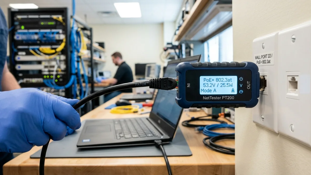
In commercial office buildings, server closets, and smart homes, unknown wall jacks can carry active 48V - 54V Power over Ethernet (PoE). Plugging a non-PoE laptop or cheap basic continuity tester into a port carrying non-standard passive PoE can instantly fry sensitive network interface chips. Using a PoE Voltage Detector & Inline Power Meter allows you to verify active voltage, IEEE standards, and polarity safely. Here is how to test PoE drops.
1. 🔬 Mode A vs Mode B PoE Pinout Polarization
- Mode A (Endspan): Power is delivered over active data pairs (Pins 1/2 and Pins 3/6) using common-mode phantom power. Typical of integrated PoE switches.
- Mode B (Midspan): Power is delivered over spare copper pairs (Pins 4/5 DC+ and Pins 7/8 DC-). Typical of standalone PoE injectors.
- 4-Pair PoE++ (802.3bt): Power is delivered across all 8 pins simultaneously to supply 60W to 90W.
2. 🔬 Passive vs Active PoE Safety Thresholds
Understanding the difference between passive and active PoE prevents expensive hardware destruction:
- Active IEEE 802.3af/at/bt PoE: The switch applies zero high voltage until a compatible 25k$\Omega$ powered device is detected during the hardware handshake. Safe for all network devices.
- Passive 24V / 48V PoE (Ubiquiti / Mikrotik Legacy): The power supply pumps continuous raw DC voltage across spare pairs with zero handshake. Plugging a standard laptop or PC into a passive PoE port can instantly destroy the computer's network interface card!
3. 🛠️ Step-by-Step PoE Drop Verification
- Plug your PoE tester (such as the Noyafa NF-8209S) into the unknown network wall jack.
- Read the LCD display: confirm whether the port is Active 802.3af/at or Passive DC.
- Verify voltage is between 48V and 54V before connecting expensive access points or security cameras.
4. 🔬 Inline Power Draw Measurement (Watts & Amps)
Advanced PoE testers (such as the Noyafa NF-8209S and Klein Scout Pro 3) feature Inline Power Monitoring: you plug the tester between the PoE switch and the security camera to measure real-time DC voltage (e.g. 52.4V), current draw (e.g. 180mA), and power consumption (e.g. 9.4 Watts).
This allows you to verify that your security cameras operate comfortably within your PoE switch's power budget during night vision infrared activation.
5. 📝 Summary: Safe PoE Testing Rules
- Always test unknown wall jacks with a PoE tester before connecting laptops.
- Verify voltage is within standard 44V - 54V operating limits.
- Protect expensive network hardware from accidental passive PoE voltage destruction.
6. 🔬 Testing Active PoE Power Delivery Under Night Vision Load
Because outdoor security cameras draw more power when their infrared (IR) night vision LEDs activate at dusk, testing active PoE voltage under simulated load with an inline meter confirms that line resistance does not drop supply voltage below the camera’s 44V minimum operating threshold.
7. 💡 Summary of Safe PoE Testing Best Practices
Always verify active PoE voltages and pinout polarization with a certified tester before connecting expensive network hardware to unknown wall jacks.
8. 🔬 Testing Midspan vs Endspan PoE Switches
Using a dedicated PoE meter confirms whether your switch supplies power via Endspan (Mode A on data pairs) or Midspan (Mode B on spare pairs), ensuring seamless compatibility with legacy IP security cameras and wireless access points.
9. 💡 Complete PoE Safety Rules
- Always test unknown wall jacks before connecting non-PoE laptops.
- Verify active PoE voltage is within standard 44V - 54V operating limits.
- Protect expensive network hardware from accidental passive PoE voltage destruction.
10. 🔬 Verifying Power over Ethernet on Ceiling Access Points
Before mounting high-performance Wi-Fi 6E or Wi-Fi 7 access points on high ceilings, plugging in an inline PoE tester confirms that the drop delivers the required 802.3at (30W) or 802.3bt (60W) power without ladder re-climbs.
11. 💡 Complete PoE Safety Summary
Always verify active PoE voltages and pinout polarization with a certified tester before connecting expensive network hardware to unknown wall jacks.
12. 🔬 Power Budget Verification for 8-Port PoE Switches
By measuring the individual wattage draw of each security camera and access point with an inline tester, you can sum the total power draw and verify that your switch operates comfortably below its total wattage ceiling.
13. 💡 Complete PoE Safety Summary
Always verify active PoE voltages and pinout polarization with a certified tester before connecting expensive network hardware to unknown wall jacks.
14. 🔬 Measuring Voltage Sag Over Long Cat6 Runs
Testing PoE voltage at the far end of long 300-foot cable runs confirms that cable loop resistance does not drop supply voltage below the camera’s minimum operating threshold during night vision activation.
15. 💡 Complete PoE Safety Summary
Always verify active PoE voltages and pinout polarization with a certified tester before connecting expensive network hardware to unknown wall jacks.
16. 💡 Final Safe PoE Testing Rules
Always verify active PoE voltages and pinout polarization with a certified tester before connecting expensive network hardware to unknown wall jacks, preventing costly equipment damage and ensuring reliable operation.
17. 💡 Power Sag Testing on 4K Security Cameras
Measuring PoE voltage under full infrared night-vision load confirms that your power supply delivers consistent, stable voltage across long cable runs, ensuring crystal-clear 24/7 security recording with zero dropouts.
18. 💡 Testing Commercial Access Point Drops
Verifying active PoE wattage before mounting access points on high ceilings ensures trouble-free installation and eliminates ladder re-climbs.